

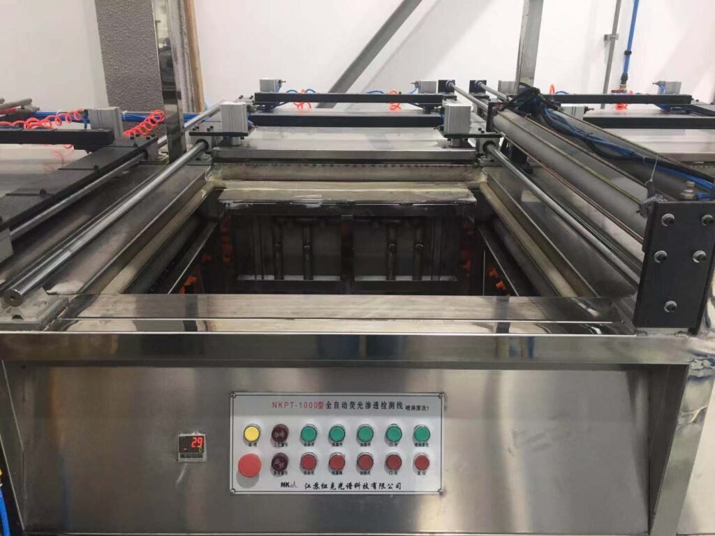
Fluorescent Penetrant Inspection Equipment: Components and Functions
Fluorescent Penetrant Inspection (FPI) relies on a coordinated series of equipment stations to apply fluorescent penetrant, remove excess penetrant, develop indications, and provide controlled ultraviolet inspection conditions. For industrial and aerospace applications, the performance of the equipment used at each stage can directly affect inspection consistency, defect detection capability, and production efficiency.
A complete fluorescent penetrant inspection equipment system may include penetrant application equipment, cleaning and rinsing stations, drying equipment, developer application systems, UV-A inspection equipment, darkrooms, control systems, and material-handling equipment.
The configuration of an FPI system depends on component dimensions, material, production volume, inspection requirements, and the required level of automation.
1. Main Components of a Fluorescent Penetrant Inspection System
Although FPI systems can be designed in many configurations, a typical industrial system may contain the following main stations:
- Penetrant application station
- Penetrant dwell station
- Excess penetrant removal and cleaning station
- Drying station
- Developer application station
- UV-A inspection station
- Darkroom or inspection booth
- Control and monitoring system
- Material handling system
Not every application requires all stations to have the same level of automation. Laboratory and low-volume applications may use manually operated equipment, while aerospace production environments may require semi-automatic or fully automatic systems.
2. Functions of Each FPI Equipment Component
Each station in an FPI system has a specific role in maintaining the inspection process.
Penetrant Application System
The penetrant application system distributes fluorescent penetrant over the surface of the component.
Depending on the component geometry and production requirements, common application methods include:
- Spray application
- Immersion
- Flow-on application
- Combined spray and immersion processes
The objective is to achieve sufficient and uniform penetrant coverage over all inspection surfaces.
For complex components, immersion can provide good surface coverage, while spray systems can offer more controlled application and reduced penetrant consumption for selected applications.
Penetrant Dwell Area
After application, the component must remain in contact with the penetrant for a specified dwell time.
The dwell area provides sufficient space for this stage of the process and may include:
- Drip collection
- Penetrant recovery
- Controlled component positioning
- Timed process control
The required dwell time depends on the applicable inspection procedure, penetrant system, material, surface condition, and defect characteristics.
Excess Penetrant Removal and Cleaning Station
After dwell, excess penetrant must be removed from the component surface without removing penetrant trapped in relevant surface-breaking discontinuities.
Depending on the process, equipment may include:
- Water rinse stations
- Spray nozzles
- Manual cleaning equipment
- Recirculation and filtration systems
- Water collection tanks
Control of water pressure, temperature, spray coverage, and cleaning time is important. Excessive cleaning can reduce the amount of penetrant remaining in discontinuities and potentially affect indication visibility.
Drying Station
Following water-based cleaning, the component needs to be dried before developer application.
Industrial FPI systems may use:
- Hot-air circulation
- Heated drying chambers
- Air knives
- Controlled drying zones
Drying parameters should be controlled according to the applicable process specification. Excessive temperature or drying time may adversely affect the inspection process, while insufficient drying can interfere with developer application.
Developer Application System
Developer helps draw trapped fluorescent penetrant back toward the surface, increasing the visibility of relevant indications under UV-A illumination.
Depending on the penetrant system and process specification, FPI equipment may incorporate:
- Dry developer application
- Wet developer application
- Developer spray systems
- Controlled developer tanks
Uniform developer coverage is important for repeatable inspection results.
For automated systems, developer application can be integrated with PLC-controlled process timing and component handling.
3. Penetrant Application Equipment
The penetrant application station is one of the most important parts of an FPI system because incomplete surface coverage can affect the entire inspection process.
Spray Application
Spray application can provide controlled coverage while allowing the equipment configuration to be adapted to different component sizes.
Automated spray systems may use fixed or moving spray nozzles to improve coverage consistency.
Immersion Application
Immersion places the component into a penetrant tank.
This method can be useful for components with complicated geometries or surfaces that are difficult to cover uniformly using conventional spray equipment.
The tank dimensions, penetrant circulation, component loading method, and drainage arrangement should be considered during system design.
Combined Application Systems
Some industrial FPI systems combine different application methods to accommodate a wider range of components.
For example, a system may use immersion for initial coverage and controlled spray application for specific process stages.
The appropriate configuration depends on component geometry, throughput, and process requirements.
4. Excess Penetrant Removal and Cleaning Equipment
Cleaning is a critical part of FPI because the objective is not simply to make the surface clean. The process must remove background penetrant while preserving penetrant trapped in relevant discontinuities.
An industrial cleaning station may include:
- Rinse tank
- Spray manifold
- Water circulation pump
- Filtration
- Drainage system
- Pressure monitoring
- Temperature monitoring
For automated FPI equipment, cleaning parameters can be incorporated into the PLC sequence to improve process repeatability.
The equipment should also provide adequate drainage so that residual water or penetrant does not interfere with subsequent processing.
5. Drying Equipment
Drying equipment removes moisture before developer application and helps establish consistent process conditions.
A typical industrial drying system may include:
- Heating elements
- Circulation fans
- Temperature sensors
- Air ducts
- Insulated drying chamber
- Automatic temperature control
The drying system should be sized according to the largest component and the required production rate.
For large aerospace components, uniform airflow and temperature distribution can be particularly important because uneven drying may result in inconsistent processing conditions across the component.
6. Developer Application Equipment
Developer application equipment should provide controlled and uniform coverage of the inspection surface.
The equipment configuration depends on the type of developer specified by the inspection procedure.
Possible configurations include:
- Developer tank
- Spray gun
- Automated spray nozzles
- Controlled circulation systems
- Developer recovery systems
For semi-automatic and fully automatic FPI lines, the developer station can be integrated with the component transfer system and PLC controls.
Process timing can also be monitored automatically to maintain consistency between batches.
7. UV-A Inspection Equipment and Darkroom
The UV-A inspection station is a critical part of fluorescent penetrant inspection because fluorescent indications must be viewed under controlled ultraviolet illumination and ambient lighting conditions.
A typical inspection area may include:
- UV-A LED lamps
- Darkroom enclosure or curtains
- White-light control
- Inspection workbench
- UV-A intensity monitoring
- Component positioning equipment
- Ventilation system
UV-A Wavelength
FPI inspection systems commonly use UV-A illumination around 365 nm.
The actual lamp specification and inspection conditions should be selected according to the applicable penetrant system, inspection procedure, and relevant standards.
UV-A Intensity
The inspection system should provide sufficient UV-A intensity at the inspection surface.
For example, some industrial FPI equipment can be configured for UV-A intensity of 4,000 µW/cm² or higher, depending on the application and specified inspection requirements.
The important point is that UV-A performance should be evaluated at the actual inspection surface, rather than only based on the nominal lamp output.
White-Light Control
Excessive visible light can reduce the contrast between fluorescent indications and the surrounding surface.
Therefore, the inspection area should provide controlled ambient lighting conditions and minimize unwanted white-light leakage.
A dedicated darkroom, enclosed inspection booth, or heavy-duty dark curtain system may be used depending on the system design.
8. FPI Control and Automation System
Modern FPI equipment can incorporate PLC-based control systems to coordinate multiple process stations.
A control system may monitor or control:
- Process timing
- Pump operation
- Spray cycles
- Tank levels
- Water temperature
- Drying temperature
- UV-A inspection conditions
- Component transfer
- Safety interlocks
- Alarm conditions
A touchscreen HMI can provide operators with a centralized interface for selecting process programs and monitoring equipment status.
For production environments, automated process sequencing can help reduce operator variation and improve repeatability.
However, automation should be matched to actual production requirements. A highly automated system is not necessarily the most appropriate solution for every application.
9. Material Handling Systems
Material handling becomes increasingly important as component size and production volume increase.
Depending on the application, FPI equipment may use:
- Manual loading
- Roller conveyors
- Overhead handling systems
- Hoists
- Hydraulic lifting platforms
- Automated transfer mechanisms
- Dedicated component fixtures
Handling equipment should be designed around the maximum component dimensions and weight.
For large components, the handling system also needs to consider drainage, accessibility, operator ergonomics, and safe positioning during inspection.
10. Manual, Semi-Automatic and Fully Automatic FPI Equipment
FPI systems can generally be classified according to their level of automation.
Manual FPI Systems
Manual systems are suitable for:
- Laboratory inspection
- Small production batches
- R&D applications
- A wide variety of component geometries
The operator performs most process steps manually.
The main advantage is flexibility, while throughput and process repeatability depend more heavily on operator procedures.
Semi-Automatic FPI Systems
Semi-automatic systems combine automated process stations with manual operations.
They may provide automated:
- Penetrant application
- Cleaning
- Drying
- Developer application
- Process timing
while allowing operators to perform loading, unloading, or visual inspection.
This configuration can be useful when production volume is moderate or when components vary significantly in size and geometry.
Fully Automatic FPI Systems
Fully automatic systems integrate multiple process stages into a coordinated production line.
They may include:
- Automatic component transfer
- Automated penetrant application
- Automatic washing
- Controlled drying
- Automated developer application
- UV-A inspection stations
- PLC process control
- Production data management
Fully automatic systems are generally considered when production volume, process consistency, traceability, and labor efficiency are major considerations.
11. How to Select FPI Equipment for Different Applications
Selecting FPI equipment should begin with the actual inspection requirements rather than simply choosing a machine model.
Important factors include:
Component Dimensions
The maximum and minimum component dimensions determine:
- Tank size
- Spray coverage
- Inspection area
- Handling equipment
- Workstation dimensions
Component Weight
Heavy components may require:
- Hydraulic lifting
- Hoists
- Special fixtures
- Reinforced tanks
- Powered transfer systems
Production Volume
Production requirements determine the appropriate degree of automation.
A system designed for two or three components per day may be significantly different from one designed for continuous high-volume production.
Inspection Requirements
The system should be configured according to the applicable inspection procedures and standards.
Requirements may influence:
- Penetrant application method
- Dwell time
- Cleaning method
- Drying conditions
- Developer method
- UV-A inspection conditions
- Process monitoring
Available Floor Space
FPI lines can occupy significant floor space because several process stations may be arranged sequentially.
The layout should account for:
- Component loading and unloading
- Operator access
- Drainage
- Ventilation
- Maintenance access
- Material flow
- Safety zones
Required Automation Level
Automation should be selected according to production volume, component variation, labor requirements, and desired process repeatability.
12. FPI Equipment for Aerospace Components
Aerospace components can require highly controlled inspection processes because components such as landing gear parts, actuators, shafts, structural components, and other critical parts may have demanding inspection procedures.
An aerospace FPI system may therefore require:
- Controlled process timing
- Stable UV-A inspection conditions
- Low ambient white light
- Controlled washing and drying
- Consistent developer application
- Process monitoring
- Safety interlocks
- Calibration and verification provisions
- Traceable process parameters
For aerospace production environments, equipment selection should be based not only on the physical size of the machine but also on the inspection procedure, applicable specifications, production volume, documentation requirements, and quality system.
13. Customized FPI Systems
There is no single FPI equipment configuration that is suitable for every component.
A customized FPI system can be designed around:
- Component dimensions
- Component weight
- Material
- Production capacity
- Process requirements
- Available workshop space
- Required automation level
- Inspection environment
- Material handling requirements
Depending on the application, a system can range from a compact manually operated setup to a fully integrated automated FPI production line.
For large or complex components, equipment stations can also be configured around the actual component loading, transfer, drainage, inspection, and unloading sequence.
Conclusion
Fluorescent Penetrant Inspection equipment is not simply a single machine. A complete FPI system consists of multiple process stations that work together to provide controlled penetrant application, cleaning, drying, developer application, and UV-A inspection.
The most appropriate configuration depends on the component, production requirements, inspection procedure, available space, and desired automation level.
For industrial and aerospace applications, important equipment considerations include UV-A performance, white-light control, process timing, cleaning and drying conditions, material handling, control systems, and system layout.
A properly configured FPI system can provide consistent processing conditions while improving inspection efficiency and supporting the documentation and process-control requirements of modern manufacturing and maintenance environments.
NEWK NDT designs and manufactures customized fluorescent penetrant inspection systems, from manually operated equipment to semi-automatic and fully automatic FPI production lines. System configurations can be developed according to component dimensions, production requirements, process specifications, and available workshop space.