

Fluorescent Penetrant Inspection (FPI) is a widely used non-destructive testing (NDT) method for detecting surface-breaking defects in non-porous materials. By using a fluorescent penetrant and controlled ultraviolet inspection conditions, FPI can reveal small cracks, laps, seams, porosity openings and other surface discontinuities that may not be visible during a conventional visual inspection.
FPI is widely applied to aerospace components, automotive parts, precision-machined components, castings, forgings, weldments and other critical components where reliable surface defect detection is required.
For manufacturers and NDT laboratories, the choice of fluorescent penetrant inspection equipment depends on component size, material, production volume, inspection procedure and required level of automation.
What Is Fluorescent Penetrant Inspection?
Fluorescent Penetrant Inspection is a liquid penetrant testing method that uses a fluorescent penetrant to locate surface-breaking discontinuities.
The penetrant enters open surface defects through capillary action. After excess penetrant is removed and a developer is applied when required by the inspection procedure, penetrant trapped in discontinuities produces visible fluorescent indications under controlled UV-A lighting.
Unlike visual inspection, FPI can make very small surface-breaking defects easier to identify.
The method is particularly suitable for non-porous materials such as:
- Aluminum alloys
- Stainless steel
- Titanium alloys
- Nickel-based alloys
- Other non-porous metals and suitable engineering materials
The actual inspection procedure should always be determined according to the applicable standard, component specification and customer requirements.
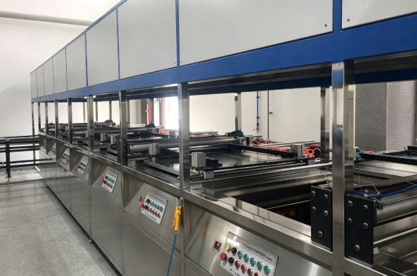
Fluorescent Penetrant Inspection Process
A typical FPI process consists of several stages. The exact sequence and process parameters may vary depending on the penetrant system, component and applicable inspection procedure.
1. Cleaning
The component surface is cleaned to remove oil, grease, dirt, scale and other contaminants.
Effective pre-cleaning is important because surface contamination can prevent penetrant from entering surface-breaking discontinuities.
2. Penetrant Application
Fluorescent penetrant is applied to the component surface using a suitable method, such as spraying, immersion or other controlled application methods.
The component must remain in contact with the penetrant for the required dwell time specified by the applicable procedure.
3. Excess Penetrant Removal
After the required dwell time, excess penetrant is removed from the component surface.
The removal method depends on the penetrant system being used. The objective is to remove background penetrant while retaining penetrant trapped inside relevant surface discontinuities.
4. Drying
The component is dried as required before the developer application or inspection stage.
Drying conditions should be controlled according to the applicable penetrant system and inspection procedure.
5. Developing
Developer is applied when required by the inspection procedure.
The developer helps draw penetrant from surface discontinuities and provides a suitable background for evaluating fluorescent indications.
6. UV-A Inspection
The component is inspected under controlled ultraviolet-A lighting in a suitable inspection area or darkroom.
Fluorescent penetrant trapped in surface-breaking defects produces visible indications, allowing trained inspectors to evaluate the component according to the applicable acceptance criteria.
What Is FPI Equipment?
FPI equipment is designed to integrate some or all stages of the fluorescent penetrant inspection process into a controlled inspection system.
A basic FPI setup may include separate equipment for:
- Pre-cleaning
- Penetrant application
- Rinsing
- Drying
- Developer application
- UV-A inspection
- Inspection lighting
- Process control
- Wastewater or effluent treatment, where required
For higher production requirements, these individual stages can be integrated into a fluorescent penetrant inspection line.
Depending on the application, an FPI system can be configured as a manual, semi-automatic or fully automated system.
Manual, Semi-Automatic and Automatic FPI Systems
Different production environments require different levels of automation.
Manual FPI System
Manual FPI systems are suitable for lower production volumes, laboratory applications, development work and applications where component varieties are high.
Operators manually transfer components between process stations and control the inspection process.
The main advantages include:
- Flexible operation
- Lower initial equipment complexity
- Suitable for different component geometries
- Easier adaptation to small production batches
Semi-Automatic FPI System
Semi-automatic FPI systems combine operator-controlled operations with automated functions.
For example, component transfer, rinsing, drying, penetrant application or process timing can be automated while other operations remain manual.
This configuration can provide a balance between flexibility and process consistency.
Fully Automatic FPI Line
Fully automatic FPI lines integrate multiple process stages into a production system.
Depending on the application, the line may include automated component handling, process timing, penetrant application, rinsing, drying, developing and inspection-area integration.
Automatic FPI systems are generally considered when production volume, repeatability, process control and traceability are important requirements.
Spray FPI vs. Immersion FPI
Penetrant can be applied using different methods depending on the component and production requirements.
Spray Application
Spray application can be suitable for large components or applications where complete immersion is impractical.
It can provide flexibility for components with large dimensions or complex production arrangements.
Immersion Application
Immersion allows the component to be surrounded by penetrant and can provide uniform coverage for suitable component geometries.
Immersion systems may be considered for batch processing or applications involving complex-shaped components.
The appropriate application method depends on factors such as component size, geometry, surface condition, production volume and the applicable inspection procedure.
Applications of Fluorescent Penetrant Inspection
FPI is commonly used for components where surface-breaking defects could affect service performance.
Typical applications include:
Aerospace Components
FPI is widely associated with aerospace inspection because many aerospace components require reliable detection of small surface discontinuities.
Typical components may include:
- Aircraft structural components
- Engine components
- Turbine components
- Machined aerospace parts
- Forged components
- Cast components
Automotive Components
FPI can be applied to selected automotive components where surface-breaking discontinuities need to be detected.
Castings and Forgings
Casting and forging processes can produce surface discontinuities that require inspection after manufacturing or machining.
FPI can be used to detect suitable surface-breaking indications on non-porous cast and forged components.
Machined Components
Machining can expose or create surface discontinuities that may require subsequent inspection.
FPI can be incorporated into inspection processes for precision-machined components where appropriate.
Large Components
Large components can require customized FPI equipment because standard inspection tanks or process stations may not provide sufficient working dimensions.
In such cases, an FPI system can be designed according to the component’s maximum length, width, height and weight.
How to Choose Fluorescent Penetrant Inspection Equipment
Selecting an FPI system requires more than simply choosing a machine size.
Important factors include:
Component Dimensions
The maximum and minimum component dimensions determine the working area, tank size, handling system and inspection space.
Component Weight
The maximum component weight affects the design of transfer systems, lifting equipment and loading arrangements.
Production Capacity
The expected number of components per shift or per day is an important factor when determining the level of automation and process configuration.
Component Material
The material and surface characteristics of the components can affect the applicable penetrant system and inspection procedure.
Component Geometry
Complex geometries may require different penetrant application, rinsing and handling solutions compared with simple flat or cylindrical components.
Required Automation Level
The system can be designed as manual, semi-automatic or fully automatic depending on production requirements and process-control needs.
Applicable Standards and Procedures
The FPI system should be designed around the applicable inspection standards and customer-specific procedures.
Commonly referenced specifications may include:
- ASTM E1417/E1417M
- AMS 2644
- AMS 2647
- Customer-specific inspection procedures
- Applicable aerospace quality requirements
The specific requirements should be confirmed for each project before equipment design and quotation.
Customized FPI Systems for Industrial Applications
Not every FPI application can be addressed with a standard machine.
Component dimensions, production volume, process sequence and customer requirements can vary significantly between projects.
A customized FPI system may therefore include:
- Customized tank dimensions
- Special component handling systems
- Spray or immersion penetrant application
- Automated or manual process stations
- Customized drying systems
- Developer application systems
- Dedicated UV-A inspection booths
- Darkroom configurations
- PLC-based control systems
- Process timing and parameter management
- Integration with existing production lines
For large or specialized components, the complete layout should be considered together with the process requirements rather than selecting individual machines separately.
FPI Equipment Manufacturer and System Engineering
An experienced FPI equipment manufacturer should be able to understand both the inspection process and the mechanical requirements of the equipment.
For customized projects, the engineering process normally starts with information such as:
- Component drawings or photographs
- Maximum and minimum component dimensions
- Component weight
- Material
- Production capacity
- Inspection area requirements
- Required inspection procedure
- Preferred automation level
- Available factory space
- Electrical and utility requirements
Based on these parameters, the FPI system can be developed around the actual production process.
Conclusion
Fluorescent Penetrant Inspection is an effective NDT method for detecting surface-breaking discontinuities in suitable non-porous materials.
The right FPI equipment depends on the component, inspection procedure, production volume and required level of automation. Manual systems can provide flexibility for smaller production volumes, while semi-automatic and fully automatic FPI lines can integrate multiple process stages for higher-volume applications.
For specialized components, a customized fluorescent penetrant inspection system can combine cleaning, penetrant application, rinsing, drying, developing and UV-A inspection into a complete process solution.
NEWK designs and manufactures customized FPI equipment and inspection systems according to component dimensions, production requirements and customer-specific inspection procedures.
Need an FPI system for your components?
Contact NEWK with your component dimensions, weight, material, production capacity and inspection requirements. Our engineering team can develop a suitable FPI equipment configuration for your application.